Installing an FD3s APEXi Power FC into a S4 FC3s

We prefer using the APEXi Power FC engine management system for tuning purposes and decided to figure out a way to use it for our Project 13B-RE Vert. We want to share this option with the RX-7 community, as an alternative to the current systems available; Haltech, MicroTech, etc.

By following this detailed 'How To', you can now install an FD3s APEXi Power FC Engine Management system into your Series 4 Mazda RX-7 ('86 - '88) with just the addition of a few items and some labor. Using this application, your commander works and you also get to keep your Oil Metering Pump & A/C! Additionally, as there is no need to remove your engine harness, the system can be un-installed and the car easily returned to stock configuration.

It is recommended that you have a good general working knowledge of electrical and mechanical systems in order to complete this installation correctly. Check and double-check everything thoroughly before attempting to start the vehicle. Failure to follow instructions can result in engine damage. Our recommendation is that you have engine management system and components professionally installed.

Banzai Racing Inc. & associates DO NOT accept any liability for injuries or adverse results arising from application of this procedure

Items Needed:

    1. FD3s APEXi Power FC: APEXi Part # 414BZ004 (NOT included in kit)
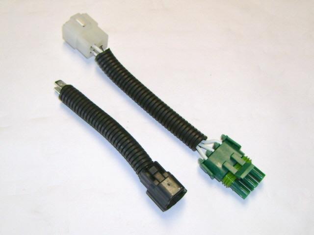
    2. Banzai Racing S4/FD PFC Harness Adapter
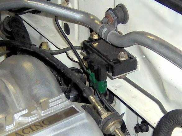
    3. Banzai Racing GM 3-Bar Map Sensor Harness Adapter
    4. Banzai Racing IAT Sensor Harness Adapter
    5. GM 3-Bar Map Sensor
    6. FD3s Intake Air Temp (IAT) Sensor
    7. Either of the following options: (NOT included in kit)
      • Additional FC Trailing Coil Pack (Recommended)
      • FD Igniter & Connector
    8. PS/2 Extension Cable (NOT included in kit & optional)
    9. Electric Fan & Relay (NOT included in kit & optional)
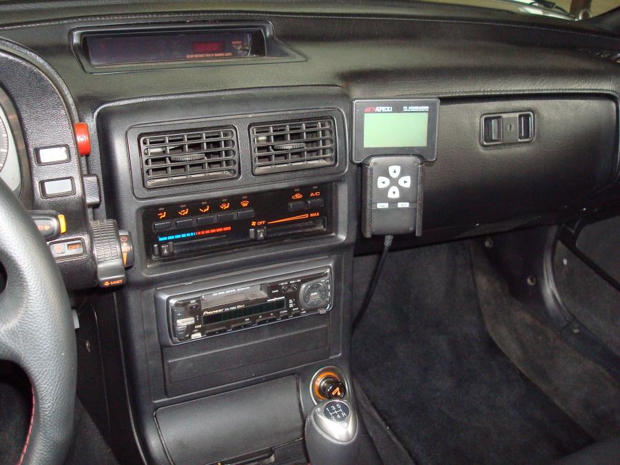
    10. Banzai Racing FC3s PFC Commander Holder (NOT included in kit & optional)

Tools Required

  1. Soldering Iron & Solder
  2. Shrink Tubing
  3. M10 x 1.25 thread Tap
  4. Basic Hand Tools

Harness Adapter, FD APEXi Power FC, PS/2 Cable & PFC Commander Holder

# 1 Harness Adapter
# 2 Adapter Installed
# 3 PFC Installed
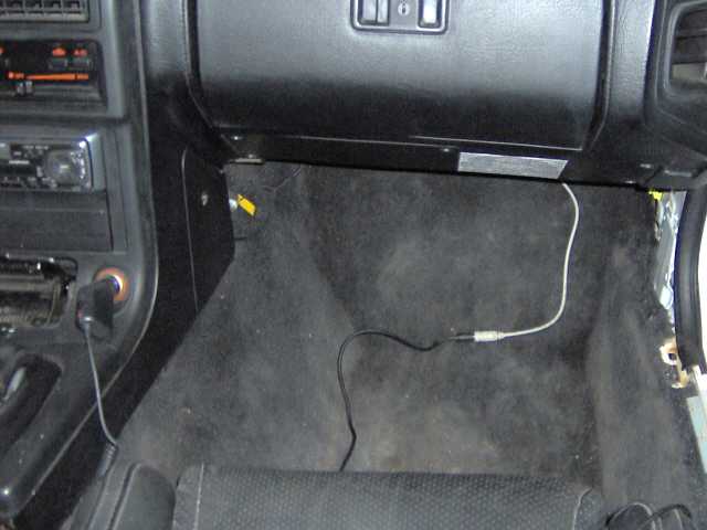
# 4 PS/2 Cable Installed
PFC Commander Holder
Connector Diagrams, Map Sensor and Air Intake Temperature Sensor & Harness Adapters
# 5 X-16 Connector
# 6 Bb-21 Connector
#7 IAT/Map Sensor Adapters
# 8 GM 3-Bar Map Sensor
# 9 Air Intake Temp Sensor
#10 FC Trailing Coil Pack

Click on images for larger view

Procedure:

  1. Disconnect the battery.
  2. Ensure that you have all items and tools required.
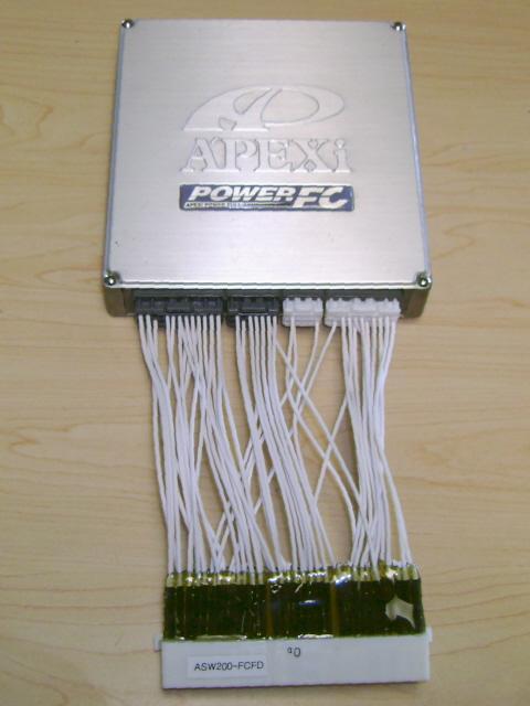
  3. Connect the Banzai Racing S4/FD PFC Harness Adapter (Pic # 1) to the APEXi Power FC (Pic # 2).
  4. Remove ECU by disconnecting from engine harness. Remove Super-AFC and/or FCD if installed at the ECU.
  5. Reconnect engine harness connectors to the Banzai Racing S4/FD PFC Harness Adapter. Engine harness is now connected to the Power FC (Pic # 3).
  6. The Speed Sensor signal originates in the instrument cluster. Connect the single 6' unterminated wire on the adapter marked SS to the Green w/ Red Striped wire at either of the following locations;
      • The Cruise Control CPU; located behind the kick panel on the driver-side of the vehicle.
      • The Power Steering CPU; located under the dash.
      • If you do not have either of these installed in your vehicle, you can connect it to the Green w/ Red striped wire exiting the back of the instrument cluster.
      • Note: Connection of this wire is optional, and is for commander display purposes only. The commander will read out in Kilometers/Hour. It does not effect the operation of the PFC.
  7. Connect the 3' unterminated wire on the adapter marked COR to the BROWN wire on the orange connector (X-16 in the FSM Pic # 5) located behind the passenger-side kick panel.
      • Ensure that you connect the COR wire to the dash harness side not to the engine harness side. This is necessary to trigger the circuit opening relay.
  8. Remove Knock Control Unit. Connect the 3' unterminated wire on the adapter marked KS to the GREY wire located on the Knock Control Unit connector (Bb-21 in FSM Pic # 6).
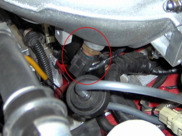
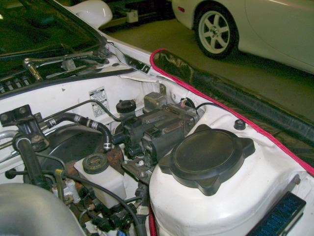
  9. Remove factory Boost Sensor (and FCD if applicable) and replace with GM 3-Bar Map Sensor (Pic # 8) using the Banzai Racing Map Sensor Adapter Harness.
  10. Install FD Intake Air Temp Sensor (Pic # 9), using Banzai Racing IAT Harness Adapter.
  11. Install modified Trailing Coil Pack with secondary igniter (Pic # 10). Click Here for complete 'How To'. (If you prefer to install the FD Igniter, Click Here for complete 'How To').
  12. Remove AFM (Air Flow Meter) and attach Air Filter directly to TID (Turbo Inlet Duct).
  13. Check all your connections.
  14. Recheck all your connections.
  15. Are you sure that your connections are correct? Recheck connections again.
  16. Reconnect the battery.
  17. Turn ignition switch to "ON" position and verify that the PFC Commander lights up.
  18. If PFC Commander does not light up, recheck connections.
  19. If you have access to a Datalogit, load supplied Base Map.
  20. Start your car, and verify you have spark at the trailing coils.
  21. As with all aftermarket engine management systems, have your car tuned by a professional.

Additional Notes:

If you have any questions about this How To, suggestions for updates please Contact Us.

Banzai Racing Inc. & associates DO NOT accept any liability for injuries or adverse results arising from application of this procedure
If necessary, click Home button to visit Banzai Racing's Website